| Back |
|---|
In thinking about the mechanism of obtaining the extra inductance in particular, I wondered how much inductance the loosely wound helix contributed over and above the extra length of wire involved. So I decided to experiment with a similar shortened dipole in which the wire of each arm was wound into a series of “hair-pins”, (which should be non inductive), rather than into a coil or helix. I had never met an antenna of this sort before, although claims have been made for various sorts of “fractal” antenna. To make a strict comparison with the “helical arms” antenna I should have done the experiment at the same wavelength, i.e. 6 metres but I had a second objective in mind, and decided to kill two birds with one stone. This second objective was to make a conveniently small 2 metre antenna for direction finding on some local interference. I felt I would be rather less conspicuous carrying a compact antenna rather than a full size 2 metre antenna down the street. I also decided to make this experimental antenna even more compact than the 6 metre one, (which was 69% of the half wavelength). I was fairly sure that all dimensions, including wavelength were completely scaleable between 6 and 2 metres.
Building neat arms of a dipole comprising half a dozen or more hair pins isn’t as easy as you might think. Any discrepancy in the length of the sides of one or more hair pins makes the antenna distinctly “banana shaped”, so I first built a wooden “bending rig”. The final shape and dimensions of my “meander line” antenna are shown in figure 1 below.

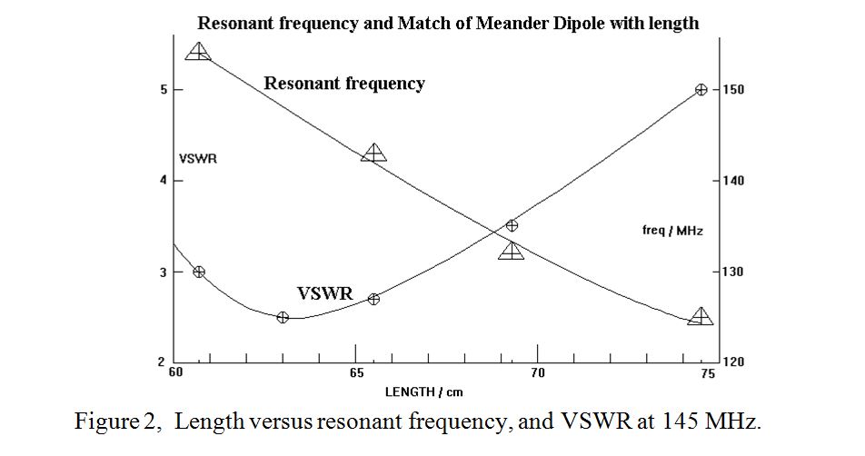
The wire used was 12 SWG, (107 thou’ diameter), enamelled copper so the arms were self supporting. The original antenna had a couple more hair pins on the end of each arm than are shown in the diagram. These were progressively trimmed off, a few mm at a time. At each overall length, the resonant frequency was measured with the feed points shorted, using a dip meter, and also the VSWR at 145 MHz. was noted using a short length of coax connected between the antenna and the SWR meter and transceiver. The results are shown in figure 2 below.

When resonant at 145 MHz., the overall length was 63 cm, compared with the normal length of a 2 m half wave dipole of 99.3 cm, i.e. a contraction to 63%. The total length of wire required in each wing was 67 cm giving a total of 134 cm, i.e. 35% more wire than a half wavelength due to winding the wire into a meander.
At resonance the VSWR was 2.5, rather worse than for the 6 metre case, but this was to be expected due to the higher contraction. Clearly some matching device would be needed if this antenna were to be required for transmission. Although the 6 metre and 2 metre cases are not strictly comparable, the similarity between the proportion of extra wire length required to achieve resonance in the two cases, (36% for the 6m case and 35% for the 2m case) implies that the inductive coupling between the turns of the widely spaced helix is negligible
In conclusion, I would say that the two experiments, (6 m and 2 m shortened dipoles), formed a most interesting project. It showed that a worthwhile reduction in the size of a dipole, (and presumably also of a reflector and directors if needed to make a beam aerial, though I haven’t tried this), can easily be achieved with a little coiling or snaking and snipping of the wire. At the same time the reduction of the aerial’s radiation resistance can greatly improve its match to 50 ohm coaxial cable.
John, G0NVZ
| Back |
|---|
